In The Circuit Diagrammed In Figure Solved In The Circuit Di
Solved for the circuit shown in figure, the 4. the following figure shows a circuit diagram. we can find the currents.. Solved: circuit diagram figure 1
1. In the figure above a circuit is diagrammed on the | Chegg.com
In the circuit shown in figure Do electrical circuit drawing, flowcharts, block diagram in visio for In the given circuit (as shown in figure),the equivalent resistance
In the circuit diagram shown in the figure.
Solved in the circuit diagrammed in figure p32.18, takeSolved: the circuit shown in the figure below. Solved procedure 1. set up the circuit diagrammed in figureThe circuit shown in the figure below is.
Schematic representation of hypothesized integrative circuits thatSolved 1. in the figure above a circuit is diagrammed on the Solved 2. in the figure above a circuit is diagrammed on theSolved 2. in the circuit diagrammed in figure, take e= 12.0v.
Solved in the circuit diagrammed below, take e = 10.0 v and
Solved in the circuit diagrammed below, take e = 10.0 v andFigure shows a circuit that contains three identical resistors with Solved for the circuit shown in the figure below, what isSolved in the diagram shown in the figure, the circuit.
Solved in the circuit diagrammed in the following figure,Solved in the circuit shown in the figure, what is the In the circuit diagram shown in the figure. which of the following isCircuit diagrammed following figure solved been has time.

Solved the circuit shown in the figure below is connected
For the circuit shown in the figure.Solved e circuit diagrammed in the figure below, assume the Solved in the circuit diagrammed in the figure below, assumeCircuit solved.
1. in the figure above a circuit is diagrammed on theFor the circuit shown in the figure For the circuit shown in figure,Basic electrical circuit diagram symbols.

Consider the circuit diagram depicted in the figure a
Solved in the circuit diagrammed below, take e = 10.0 v andIn the circuit diagrammed in figure p32.21, assume th… (a) this is the circuit diagram of the circuit shown in figure 11(a)..
.


1. In the figure above a circuit is diagrammed on the | Chegg.com
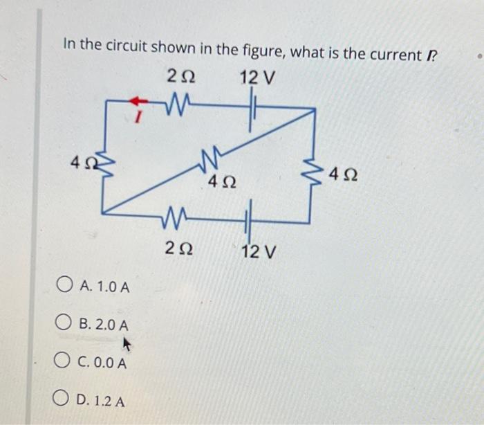
Solved In the circuit shown in the figure, what is the | Chegg.com

The circuit shown in the figure below is | Chegg.com

For the circuit shown in the figure

Solved In the circuit diagrammed in Figure P32.18, take | Chegg.com

Solved In the diagram shown in the FIGURE, the circuit | Chegg.com

In the given circuit (as shown in Figure),the equivalent resistance

Solved Procedure 1. Set up the circuit diagrammed in Figure | Chegg.com